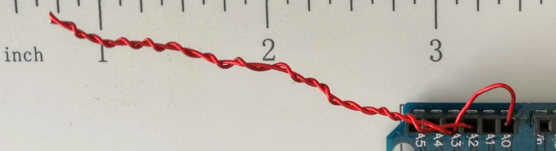
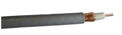
<html> <p>If you search through an electrical engineering textbook, you probably aren’t going to find the phrase “gimmick capacitor” but every old ham radio operator knows about them. They come in handy when you need a very small capacitor of unknown value. For example, if you are trying to balance the stray capacitance in a circuit, you might not know exactly what value you need, but you know it won’t be very much. That’s when you want a gimmick capacitor.</p> <p>A gimmick capacitor is made by taking two strands of insulated wire and twisting them together; the length and the tightness of the twist determine the capacitance. Tightening or loosening the twist, or trimming some of the wire off, makes it tunable.</p> <p>These are most commonly found in RF equipment or high-speed logic because of the small capacitance involved — usually about 1 to 2 pF per inch of twist or so. The thicker the insulation, the less capacitance you’ll get, so it is common to use magnet wire or something else with a thin insulating layer. You can take this one step further and decrease the spacing by stripping down one wire as long as it isn’t going to touch anything else.</p> <p>Obviously, the insulation needs to be good enough for the voltage on them, an important consideration in tube circuits, for instance. But other than that, a gimmick capacitor is a straightforward tool to have in your box of design tricks. Can we take this further?</p> <h2>PC Board Gimmicks</h2> <p>You might wonder if the technique can be applied to PC boards. The answer is yes — sort of. Unless you use very thin boards, or thin layers in multilayer boards, it takes a lot of board real estate to get even a small capacitance. Also, typical PCB material can change over time with moisture or other effects. Practically, unless you use special board material and thicknesses, it isn’t very useful. There has been work on laying out <a href=„http://smirc.stanford.edu/papers/isscc98s-Hirad.pdf“ target=„_blank“>linear capacitors on IC substrates using fractals</a>, but we aren’t sure how that would translate into a PCB layout. We’ve seen lots of other PC trace components like antennas, shunt resistors, inductors, and transmission lines.</p> <p><a href=„https://hackadaycom.files.wordpress.com/2018/06/img_20180625_154138.jpg“ target=„_blank“><img data-attachment-id=„313993“ data-permalink=„https://hackaday.com/2018/07/03/these-capacitors-are-a-cheap-gimmick/bty-21/“ data-orig-file=„https://hackadaycom.files.wordpress.com/2018/06/img_20180625_154138.jpg“ data-orig-size=„1734,473“ data-comments-opened=„1“ data-image-meta=„{"aperture":"2.2","credit":"","camera":"FRD-L04","caption":"bty","created_timestamp":"1529941298","copyright":"","focal_length":"4.5","iso":"100","shutter_speed":"0.016667","title":"bty","orientation":"1"}“ data-image-title=„bty“ data-image-description=„“ data-medium-file=„https://hackadaycom.files.wordpress.com/2018/06/img_20180625_154138.jpg?w=400“ data-large-file=„https://hackadaycom.files.wordpress.com/2018/06/img_20180625_154138.jpg?w=800&h=218“ class=„size-large wp-image-313993“ src=„https://hackadaycom.files.wordpress.com/2018/06/img_20180625_154138.jpg?w=800&h=218“ alt=„“ width=„800“ height=„218“ srcset=„https://hackadaycom.files.wordpress.com/2018/06/img_20180625_154138.jpg?w=800&h=218 800w, https://hackadaycom.files.wordpress.com/2018/06/img_20180625_154138.jpg?w=1600&h=436 1600w, https://hackadaycom.files.wordpress.com/2018/06/img_20180625_154138.jpg?w=250&h=68 250w, https://hackadaycom.files.wordpress.com/2018/06/img_20180625_154138.jpg?w=400&h=109 400w, https://hackadaycom.files.wordpress.com/2018/06/img_20180625_154138.jpg?w=768&h=209 768w“ sizes=„(max-width: 800px) 100vw, 800px“/></a></p> <p>You can see I made a gimmick just bigger than two inches. I then went looking for something around the lab that had the ability to measure such a small capacitor. The component tester couldn’t. I have a nice digital multimeter that has a special plug-in for measuring capacitors and thermocouples, but it wouldn’t reliably read anything under 25 pF. I was thinking about building up a circuit to test when I realized <a href=„https://hackaday.com/2014/01/22/capacitance-measurement-with-the-arduino-uno/“>I should search Hackaday first</a>.</p> <h2>Hackaday Saves the Day</h2> <p>[Jonathan’s] capacitance meter is just what I needed and I even threw it out to an Arduino that was already hooked up using the Arduino Create web interface, so that was easy. I actually used the newer “Mark II” code but it works the same for the low values I was measuring. I calibrated with a garden variety 10 pF ceramic. It probably isn’t that accurate, but I really only wanted to see the change more than the actual value, so I thought this was sufficient.</p> <p><a href=„https://hackadaycom.files.wordpress.com/2018/06/gimmick.png“ class=„c2“ target=„_blank“><img data-attachment-id=„313948“ data-permalink=„https://hackaday.com/2018/07/03/these-capacitors-are-a-cheap-gimmick/gimmick/“ data-orig-file=„https://hackadaycom.files.wordpress.com/2018/06/gimmick.png?w=800&h=261“ data-orig-size=„800,261“ data-comments-opened=„1“ data-image-meta=„{"aperture":"0","credit":"","camera":"","caption":"","created_timestamp":"0","copyright":"","focal_length":"0","iso":"0","shutter_speed":"0","title":"","orientation":"0"}“ data-image-title=„gimmick“ data-image-description=„“ data-medium-file=„https://hackadaycom.files.wordpress.com/2018/06/gimmick.png?w=800&h=261?w=400“ data-large-file=„https://hackadaycom.files.wordpress.com/2018/06/gimmick.png?w=800&h=261?w=800“ class=„aligncenter size-full wp-image-313948“ src=„https://hackadaycom.files.wordpress.com/2018/06/gimmick.png?w=800&h=261“ alt=„“ width=„800“ height=„261“ srcset=„https://hackadaycom.files.wordpress.com/2018/06/gimmick.png 800w, https://hackadaycom.files.wordpress.com/2018/06/gimmick.png?w=250&h=82 250w, https://hackadaycom.files.wordpress.com/2018/06/gimmick.png?w=400&h=131 400w, https://hackadaycom.files.wordpress.com/2018/06/gimmick.png?w=768&h=251 768w“ sizes=„(max-width: 800px) 100vw, 800px“/></a></p> <p>The two inch (call it 6 cm) gimmick reads about 5.5 pF. That might not be totally accurate, but I was expecting about 4.5 pF and the magnet wire insulation is quite thin, so it’s in the right ballpark. Let’s take it as a baseline to measure change. I then cut about 1.5 cm of the capacitor away — about 25% — and the reading became 3.7 pF. Another centimeter brought it down to 2.6 pF.</p> <p>Of course, hand-wound pitch isn’t very accurate, nor were my cuts or measurements, but that works out to just around 1 pF per centimeter. Obviously, your results are going to depend on your winding and the kind of wire you use. [Harry Lythall] <a href=„http://213.114.131.21/begin/gimmik-0.htm“ target=„_blank“>suggests</a> folding a single piece of wire, holding it with pliers, and twisting. Then you cut the loop when you are done.</p> <h2>That’s a Wrap</h2> <p><a href=„https://hackadaycom.files.wordpress.com/2018/06/rg8x.jpg“ target=„_blank“><img data-attachment-id=„313992“ data-permalink=„https://hackaday.com/2018/07/03/these-capacitors-are-a-cheap-gimmick/rg8x/“ data-orig-file=„https://hackadaycom.files.wordpress.com/2018/06/rg8x.jpg“ data-orig-size=„1040,302“ data-comments-opened=„1“ data-image-meta=„{"aperture":"0","credit":"","camera":"","caption":"","created_timestamp":"0","copyright":"","focal_length":"0","iso":"0","shutter_speed":"0","title":"","orientation":"0"}“ data-image-title=„rg8x“ data-image-description=„“ data-medium-file=„https://hackadaycom.files.wordpress.com/2018/06/rg8x.jpg?w=400“ data-large-file=„https://hackadaycom.files.wordpress.com/2018/06/rg8x.jpg?w=800“ class=„alignleft wp-image-313992 size-thumbnail“ src=„https://hackadaycom.files.wordpress.com/2018/06/rg8x.jpg?w=250&h=73“ alt=„“ width=„250“ height=„73“ srcset=„https://hackadaycom.files.wordpress.com/2018/06/rg8x.jpg?w=250&h=73 250w, https://hackadaycom.files.wordpress.com/2018/06/rg8x.jpg?w=500&h=146 500w, https://hackadaycom.files.wordpress.com/2018/06/rg8x.jpg?w=400&h=116 400w“ sizes=„(max-width: 250px) 100vw, 250px“/></a>It is easy to forget that any two conductors near each other will have capacitance. Another common makeshift capacitor is a length of coax with connections at one end and open at the other. RG-8, for example, is about 30 pF per foot of cable. There’s even an <a href=„https://mikeyancey.com/hamcalc/capacitors_from_coax.php“ target=„_blank“>online calculator that will tell you how much coax you need</a> for any given value. This varies by coax type, of course, so remember to cut a little long and trim!</p> <p>The next time you need a small adjustable capacitor — especially in a lab setting — don’t forget about the gimmick. Be sure to experiment with different kinds of wire if you are trying for larger values. We’ve seen this trick used in <a href=„https://hackaday.com/2017/03/30/real-world-rf-filter-design-and-construction/“>RF filters</a>. In the case of the gimmick, you may be thinking small, but when you are really looking for <a href=„https://hackaday.com/2015/08/02/homemade-high-voltage-caps/“>high voltage capacitors</a>, you can make those, too.</p> </html>