TrigBoard - Kevin Darrah Wiki
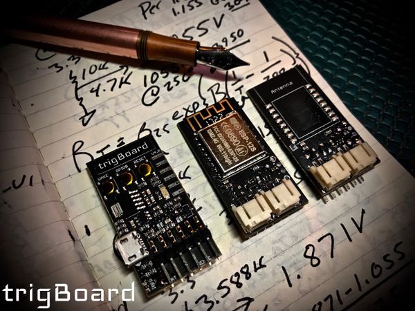
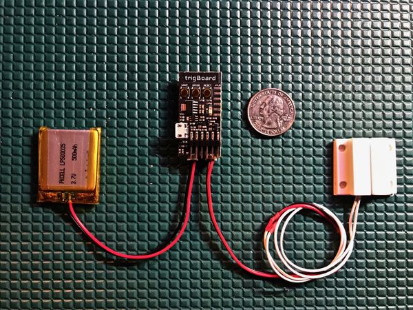
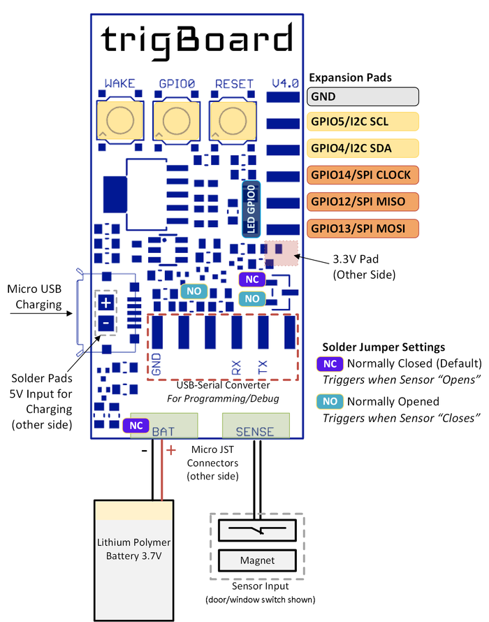
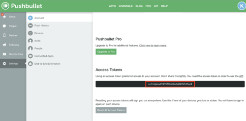
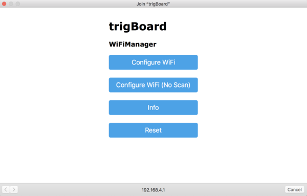
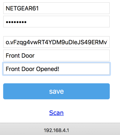
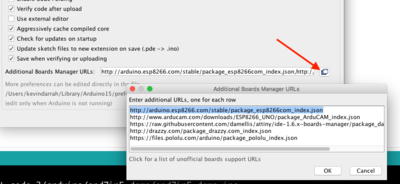
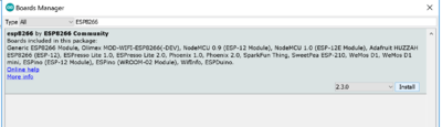
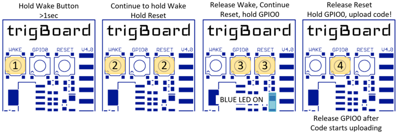
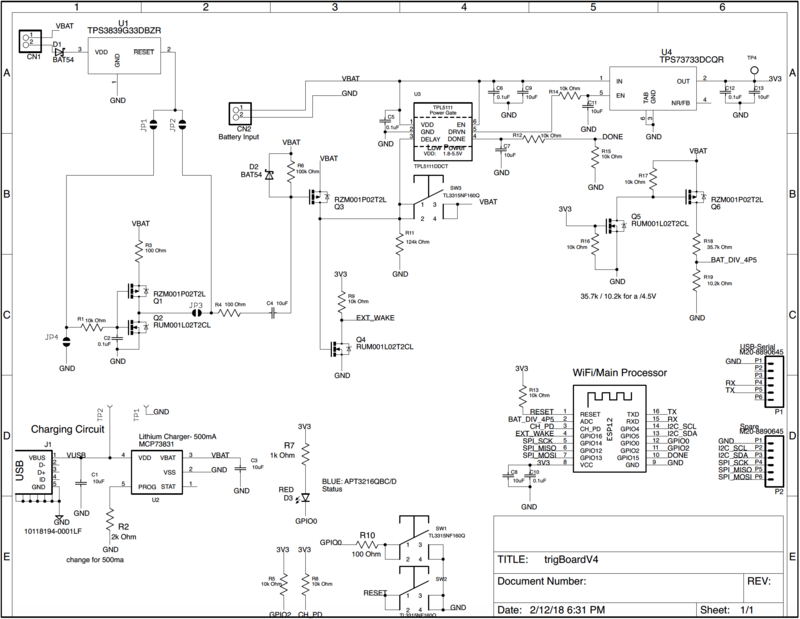
<html> <p>…Back to <a href=„http://www.kevindarrah.com/wiki/index.php?title=Projects:“ title=„Projects:“>Projects:</a></p> <p><a href=„http://www.kevindarrah.com/wiki/index.php?title=File:TrigBoardfountain2.jpg“ class=„image“><img alt=„TrigBoardfountain2.jpg“ src=„http://www.kevindarrah.com/wiki/images/thumb/d/d8/TrigBoardfountain2.jpg/600px-TrigBoardfountain2.jpg“ width=„600“ height=„450“ srcset=„/wiki/images/thumb/d/d8/TrigBoardfountain2.jpg/900px-TrigBoardfountain2.jpg 1.5x, /wiki/images/thumb/d/d8/TrigBoardfountain2.jpg/1200px-TrigBoardfountain2.jpg 2x“/></a></p> <p>The trigBoard is an IoT project that does one thing - it pushes you a notification triggered by a digital input. Well, it's much more than that, but this is the inspiration. I wanted to design a WiFi board that essentially sleeps most of its life, but when that door switch, flood sensor, motion sensor, etc.. gets triggered, I just want a notification immediately on my phone. And that's about it… a perfect IoT device in the background doing its job.</p> <div id=„toc“ class=„toc“> <p> <h2>Contents</h2> </p> <ul><li class=„toclevel-1 tocsection-1“><a href=„http://www.kevindarrah.com/wiki/index.php?title=TrigBoard#Latest_Release_Version_4“>1 Latest Release Version 4</a> <ul><li class=„toclevel-2 tocsection-2“><a href=„http://www.kevindarrah.com/wiki/index.php?title=TrigBoard#What_is_the_trigBoard.3F“>1.1 What is the trigBoard?</a></li> <li class=„toclevel-2 tocsection-3“><a href=„http://www.kevindarrah.com/wiki/index.php?title=TrigBoard#Purchase_trigBoard“>1.2 Purchase trigBoard</a></li> <li class=„toclevel-2 tocsection-4“><a href=„http://www.kevindarrah.com/wiki/index.php?title=TrigBoard#Out_of_the_Box_Setup“>1.3 Out of the Box Setup</a></li> <li class=„toclevel-2 tocsection-5“><a href=„http://www.kevindarrah.com/wiki/index.php?title=TrigBoard#Operation“>1.4 Operation</a></li> <li class=„toclevel-2 tocsection-6“><a href=„http://www.kevindarrah.com/wiki/index.php?title=TrigBoard#Base_Firmware“>1.5 Base Firmware</a></li> <li class=„toclevel-2 tocsection-7“><a href=„http://www.kevindarrah.com/wiki/index.php?title=TrigBoard#Projects“>1.6 Projects</a></li> <li class=„toclevel-2 tocsection-8“><a href=„http://www.kevindarrah.com/wiki/index.php?title=TrigBoard#Testing_and_Programming“>1.7 Testing and Programming</a></li> <li class=„toclevel-2 tocsection-9“><a href=„http://www.kevindarrah.com/wiki/index.php?title=TrigBoard#Tutorials“>1.8 Tutorials</a> <ul><li class=„toclevel-3 tocsection-10“><a href=„http://www.kevindarrah.com/wiki/index.php?title=TrigBoard#V4_Hardware_Walkthrough“>1.8.1 V4 Hardware Walkthrough</a></li> <li class=„toclevel-3 tocsection-11“><a href=„http://www.kevindarrah.com/wiki/index.php?title=TrigBoard#Sending_to_SLACK“>1.8.2 Sending to SLACK</a></li> <li class=„toclevel-3 tocsection-12“><a href=„http://www.kevindarrah.com/wiki/index.php?title=TrigBoard#Clear_Sky_Checker_-_openweathermap.org“>1.8.3 Clear Sky Checker - openweathermap.org</a></li> <li class=„toclevel-3 tocsection-13“><a href=„http://www.kevindarrah.com/wiki/index.php?title=TrigBoard#Add_a_Camera“>1.8.4 Add a Camera</a></li> </ul></li> <li class=„toclevel-2 tocsection-14“><a href=„http://www.kevindarrah.com/wiki/index.php?title=TrigBoard#Schematic“>1.9 Schematic</a></li> <li class=„toclevel-2 tocsection-15“><a href=„http://www.kevindarrah.com/wiki/index.php?title=TrigBoard#Disclaimer“>1.10 Disclaimer</a></li> </ul></li> </ul></div> <p><a href=„http://www.kevindarrah.com/wiki/index.php?title=File:TrigBoard_overhead.jpg“ class=„image“><img alt=„TrigBoard overhead.jpg“ src=„http://www.kevindarrah.com/wiki/images/thumb/a/a5/TrigBoard_overhead.jpg/600px-TrigBoard_overhead.jpg“ width=„600“ height=„450“ srcset=„/wiki/images/thumb/a/a5/TrigBoard_overhead.jpg/900px-TrigBoard_overhead.jpg 1.5x, /wiki/images/thumb/a/a5/TrigBoard_overhead.jpg/1200px-TrigBoard_overhead.jpg 2x“/></a></p> <ul><li>Simple IoT development board that was designed to trigger „Push Notifications“ on a smart phone/tablet based on a trigger event.</li> <li>Unique low-power front-end to enable sub 1uA sleep current - uses a pulse to trigger wake-up, so even if door/window/etc is opened, the same ultra low currents can be maintained. Compare to standard pull-up/down resistor based digital input designs with significantly higher leakage current.</li> <li>The board will wake itself up once an hour to check the battery voltage - if running low, a push notification is sent to warn the user. This timer can be used to check other things as well - temperature changes, accelerometers, or other environmental sensors.</li> <li>Based on ESP8266 WiFi Module (ESP-12S) - all source code is available for download and developed in the popular Arduino IDE.</li> <li>Battery Input can be any Lithium Polymer 3.7V - standard micro JST connector jack is used (please double check polarity),any of <a rel=„nofollow“ class=„external text“ href=„https://www.adafruit.com/category/574“>these</a> would work nicely.</li> <li>Sensor input to trigger the „Wake Up“ is a simple passive switch. Typically a standard magnetic door/window switch is used and the board can be configured to wake on the „opening“ (Normally Closed) or „closure“ (Normally Open) of the contact. Solder jumpers set this - Normally Closed is Default, so standard door/window switches wake the board up when opened.</li> <li>Battery Charging On-Board via MicroUSB - set for 4.2V at 500mA. 5V input pads broken out for energy harvesting experimentation.</li> <li>Dimensions only 0.8„ x 1.6 “ (20.32mm x 40.64mm)</li> </ul><p><a href=„http://www.kevindarrah.com/wiki/index.php?title=File:Trigboard_Diagram.png“ class=„image“><img alt=„Trigboard Diagram.png“ src=„http://www.kevindarrah.com/wiki/images/thumb/c/c0/Trigboard_Diagram.png/700px-Trigboard_Diagram.png“ width=„700“ height=„890“ srcset=„/wiki/images/thumb/c/c0/Trigboard_Diagram.png/1050px-Trigboard_Diagram.png 1.5x, /wiki/images/thumb/c/c0/Trigboard_Diagram.png/1400px-Trigboard_Diagram.png 2x“/></a></p> <h2>What is the trigBoard?</h2> <pre>Demo and Base Code [Released 12/18/17] walkthrough </pre> <iframe src=„http://www.youtube.com/embed/onrLyTaUqbw?“ width=„560“ height=„315“ frameborder=„0“ allowfullscreen=„true“> </iframe> <h2>Purchase trigBoard</h2> <p><a href=„https://www.tindie.com/stores/kdcircuits“ rel=„nofollow“><img alt=„Tindie-larges.png“ src=„http://www.kevindarrah.com/wiki/images/4/4d/Tindie-larges.png“ width=„338“ height=„176“/></a></p> <h2>Out of the Box Setup</h2> <p>The setup for getting the trigBoard installed is very easy. The base firmware that comes loaded on the board is ready to work with Pushbullet. This is a service that has many other features, but for the trigBoard, this offered a simple way for the push notification to be triggered using an „off the shelf“ platform. It's all simple to get setup - just follow these steps:</p> <ol><li>Push Bullet Setup <ol><li>Go here: <a rel=„nofollow“ class=„external free“ href=„https://www.pushbullet.com“>https://www.pushbullet.com</a> and sign-in. You can do this (currently) with Facebook or Google - I use Google</li> <li>Download the mobile app for iOS or Android, and sign in. You can also setup push notifications for your computers as well by installing the browser plugins. You may even like getting the desktop notifications better.</li> <li>Go back to your account page, click on settings, then „Generate Access Token“. Copy the entire „o.xxxxx“ token and save this somewhere. This is what you will use to provision the trigBoard to your Push Bullet account. I actually use the same token for every trigBoard.</li> </ol></li> </ol><p><a href=„http://www.kevindarrah.com/wiki/index.php?title=File:PushBulletToken.png“ class=„image“><img alt=„PushBulletToken.png“ src=„http://www.kevindarrah.com/wiki/images/thumb/6/65/PushBulletToken.png/500px-PushBulletToken.png“ width=„500“ height=„247“ srcset=„/wiki/images/thumb/6/65/PushBulletToken.png/750px-PushBulletToken.png 1.5x, /wiki/images/thumb/6/65/PushBulletToken.png/1000px-PushBulletToken.png 2x“/></a></p> <ol><li>trigBoard Setup <ol><li>You will need a 3.7V Lithium Battery - fully charged will be 4.2V. The battery connects to the trigBoard using a standard micro-JST connector. Any of <a rel=„nofollow“ class=„external text“ href=„https://www.adafruit.com/category/574“>these</a> would work. Battery estimator calculations coming soon, but I typically use a ~1000mAh battery on all my doors/windows… that yields very long battery life.</li> <li>Then for the sensor input, this can be a simple passive switch, but I use magnetic door/window sensors like <a rel=„nofollow“ class=„external text“ href=„https://www.amazon.com/dp/B00LYCUSBY/ref=sxbs_sxwds-stvp_1?pf_rd_m=ATVPDKIKX0DER&pf_rd_p=3341940462&pd_rd_wg=Nbhph&pf_rd_r=0DBSJ3Q6TNF9BDV32CXG&pf_rd_s=desktop-sx-bottom-slot&pf_rd_t=301&pd_rd_i=B00LYCUSBY&pd_rd_w=98468&pf_rd_i=magnetic+door+sensor&pd_rd_r=83aa0c34-3901-4f4f-bf19-1fc2ae849c87&ie=UTF8&qid=1512593794&sr=1“>these</a> and then solder the wires to the JST connector. For the JST side, I go with <a rel=„nofollow“ class=„external text“ href=„https://www.amazon.com/gp/product/B0167X4D9M/ref=oh_aui_search_detailpage?ie=UTF8&psc=1“>these</a>. It would be nice to find magnetic switches with the JST connectors already soldered on… Also, keep in mind that by default, the board is configured to „Wake“ when the contact opens. This is the normally closed mode of operation. If it is desired to wake on a closure of the contact, then see the diagram above and desolder the NC solder jumpers (ensure they are open) and solder across the NO jumpers (make sure they are closed). That default NC configuration was chosen because the magnetic door/window sensors are closed when the magnet is in proximity, so the trigBoard wakes up when the door/window is opened.</li> <li>IMPORTANT - The trigBoard performs a calibration on the built-in timer on power-up. The sensor input must be closed when powered up, otherwise the 1hr timer will not be accurate. You basically just need to have the door/window closed before the battery is plugged in.</li> <li>Before mounting the trigBoard in it's final location, a simple bench test is helpful to make sure everything is setup. With the battery and sensor plugged in, simply bring the magnet close to the sensor, hold there for a second, then pull away. You should see the blue LED on the board go solid. If you don't have the sensor part yet or plan on using something else, just press and hold the 'wake' button on the board for a second. Since this is the first time the board has been powered up at this location, it will need to be provisioned for your network. When that LED is ON, you have 2minutes to provision before it gives up and goes back to sleep. <ol><li>Go to your network settings, to expose available WiFi networks. You should see „trigBoard“. Go ahead and connect to this network. A captive portal window should automatically pop up:</li> </ol></li> </ol></li> </ol><p><a href=„http://www.kevindarrah.com/wiki/index.php?title=File:TrigBoardcaptive.png“ class=„image“><img alt=„TrigBoardcaptive.png“ src=„http://www.kevindarrah.com/wiki/images/thumb/5/5c/TrigBoardcaptive.png/600px-TrigBoardcaptive.png“ width=„600“ height=„383“ srcset=„/wiki/images/thumb/5/5c/TrigBoardcaptive.png/900px-TrigBoardcaptive.png 1.5x, /wiki/images/thumb/5/5c/TrigBoardcaptive.png/1200px-TrigBoardcaptive.png 2x“/></a></p> <p>If you don't see a captive portal, you may need to open your browser and attempt to load a website. Try to google something. If you still don't see the portal, then you can try connecting directly to the board - in the browser, type in 192.168.4.1 in the address box. That should connect you to the portal. If you're still having problems, try disconnecting the battery from the board and allow the trigBoard SSID to fade away from the available networks on your computer. Then plug the battery back in and try again. Seems that on windows this may take more than one try.</p> <p>Click configure, and select the network that you trigBoard to use and enter in the password. You'll now see where you want to enter in the Pushbullet „o.xxx“ access token. Then you can give the board a name, and a trigger message. Once that's entered in, click Save and you're all done! You should now get a push notification to your phone (when you installed the app, make sure you gave permission).</p> <p><a href=„http://www.kevindarrah.com/wiki/index.php?title=File:Captivesetup.png“ class=„image“><img alt=„Captivesetup.png“ src=„http://www.kevindarrah.com/wiki/images/thumb/9/90/Captivesetup.png/400px-Captivesetup.png“ width=„400“ height=„450“ srcset=„/wiki/images/thumb/9/90/Captivesetup.png/600px-Captivesetup.png 1.5x, /wiki/images/9/90/Captivesetup.png 2x“/></a></p> <p>Note - the free version of Pushbullet limits the maximum number of messages per month. I have so many of these boards installed, that I upgraded… the monthly fee (at the time of writing this) was very reasonable.</p> <h2>Operation</h2> <iframe src=„http://www.youtube.com/embed/37YZulkoMB0?“ width=„560“ height=„315“ frameborder=„0“ allowfullscreen=„true“> </iframe> <h2>Base Firmware</h2> <p>Note! the board is preloaded with the base firmware out-of-the-box, but if you want to develop/modify your own firmware, this section will go through the steps for getting the base code to compile.</p> <p>Base Firmware Downloads:</p> <pre><a rel=„nofollow“ class=„external text“ href=„http://kevindarrah.com/micro/Pusher/trigBoardRelease_10_08_18.zip“>Released 10/08/18</a> Changes: updated code slightly to work with latest version of libs and ESP core Tested on Arduino v1.8.7, ESP core v2.4.2, WiFi Manager v0.14.0, Arduino JSON v5.13.3 </pre> <pre><a rel=„nofollow“ class=„external text“ href=„http://kevindarrah.com/micro/Pusher/trigBoardRelease_12_18_17.zip“>Released 12/18/17</a> Tested on Arduino v1.8.3, ESP core v2.3.0, WiFi Manager v0.12.0, Arduino JSON v5.11.1 </pre> <p>Base Firmware Developed on Arduino IDE - can download <a rel=„nofollow“ class=„external text“ href=„https://www.arduino.cc/en/Main/Software“>Here</a> or <a rel=„nofollow“ class=„external text“ href=„https://www.arduino.cc/en/Main/OldSoftwareReleases#previous“>Here for previous versions</a></p> <p>Then you'll find that the code does not compile and that's because you need several libraries and the board manager installed. Here's what you need:</p> <p>First, go to File>>Preferences and add this URL to to the „Additional Boards Manager URL“. <a rel=„nofollow“ class=„external free“ href=„http://arduino.esp8266.com/stable/package_esp8266com_index.json“>http://arduino.esp8266.com/stable/package_esp8266com_index.json</a></p> <p><a href=„http://www.kevindarrah.com/wiki/index.php?title=File:BoardsManagerURLnewCore.png“ class=„image“><img alt=„BoardsManagerURLnewCore.png“ src=„http://www.kevindarrah.com/wiki/images/thumb/5/51/BoardsManagerURLnewCore.png/400px-BoardsManagerURLnewCore.png“ width=„400“ height=„184“ srcset=„/wiki/images/thumb/5/51/BoardsManagerURLnewCore.png/600px-BoardsManagerURLnewCore.png 1.5x, /wiki/images/thumb/5/51/BoardsManagerURLnewCore.png/800px-BoardsManagerURLnewCore.png 2x“/></a></p> <p>Now, the ESP8266 boards will be available for installation. Go to Tools>>Board>>Boards Manager… Search for ESP8266, and go ahead and click install.</p> <p><a href=„http://www.kevindarrah.com/wiki/index.php?title=File:ESP8266Install.png“ class=„image“><img alt=„ESP8266Install.png“ src=„http://www.kevindarrah.com/wiki/images/thumb/0/0c/ESP8266Install.png/400px-ESP8266Install.png“ width=„400“ height=„115“ srcset=„/wiki/images/thumb/0/0c/ESP8266Install.png/600px-ESP8266Install.png 1.5x, /wiki/images/thumb/0/0c/ESP8266Install.png/800px-ESP8266Install.png 2x“/></a></p> <p>After the boards are installed, you can select any of the ESP8266 boards out there from the Board Selection. For the trigBoard, I have been using the Adafruit Huzzah, here are my settings. Note that I always upload as fast as possible:</p> <p><a href=„http://www.kevindarrah.com/wiki/index.php?title=File:TrigHuzzahSettings.png“ class=„image“><img alt=„TrigHuzzahSettings.png“ src=„http://www.kevindarrah.com/wiki/images/2/2b/TrigHuzzahSettings.png“ width=„400“ height=„533“/></a></p> <p>These settings also work:</p> <p><a href=„http://www.kevindarrah.com/wiki/index.php?title=File:EspsettingNodeMCU.png“ class=„image“><img alt=„EspsettingNodeMCU.png“ src=„http://www.kevindarrah.com/wiki/images/thumb/f/f0/EspsettingNodeMCU.png/400px-EspsettingNodeMCU.png“ width=„400“ height=„524“ srcset=„/wiki/images/thumb/f/f0/EspsettingNodeMCU.png/600px-EspsettingNodeMCU.png 1.5x, /wiki/images/f/f0/EspsettingNodeMCU.png 2x“/></a></p> <p>Next, you'll need to install the specific Arduino Libraries I'm using in the base code. The first one is is the <a rel=„nofollow“ class=„external text“ href=„https://github.com/tzapu/WiFiManager“>WiFi Manager by tzapu</a> - the easiest way to install the library is to go to Sketch>>Include Library>>Manage Libraries. Then type in WIFImanager. Go ahead and install the library.</p> <p><a href=„http://www.kevindarrah.com/wiki/index.php?title=File:WiFiManager.png“ class=„image“><img alt=„WiFiManager.png“ src=„http://www.kevindarrah.com/wiki/images/thumb/5/55/WiFiManager.png/400px-WiFiManager.png“ width=„400“ height=„106“ srcset=„/wiki/images/thumb/5/55/WiFiManager.png/600px-WiFiManager.png 1.5x, /wiki/images/thumb/5/55/WiFiManager.png/800px-WiFiManager.png 2x“/></a></p> <p>Do the same for the <a rel=„nofollow“ class=„external text“ href=„http://arduinojson.org/“>Arduino JSON library by Benoit Blanchon</a> - can just search for JSON.</p> <p><a href=„http://www.kevindarrah.com/wiki/index.php?title=File:ArduinoJSON.png“ class=„image“><img alt=„ArduinoJSON.png“ src=„http://www.kevindarrah.com/wiki/images/thumb/d/d5/ArduinoJSON.png/400px-ArduinoJSON.png“ width=„400“ height=„149“ srcset=„/wiki/images/thumb/d/d5/ArduinoJSON.png/600px-ArduinoJSON.png 1.5x, /wiki/images/thumb/d/d5/ArduinoJSON.png/800px-ArduinoJSON.png 2x“/></a></p> <p>Then that should be it - the other libraries are automatically installed with the ESP8266 board manager.</p> <p>See the „Testing and Programming“ section below for information on loading the code over a wired USB-Serial connection. The other option is to load code wirelessly „OTA - Over the Air“. In the „trigBoard Operation“ section this is shown.</p> <h2>Projects</h2> <p><a href=„http://www.kevindarrah.com/wiki/index.php?title=WeatherBoard“ title=„WeatherBoard“>WeatherBoard</a> BME280 and LMT01 Weather Station</p> <p><a href=„http://www.kevindarrah.com/wiki/index.php?title=EPaperBoard“ title=„EPaperBoard“>EPaperBoard</a> E-Paper Display</p> <p><a href=„http://www.kevindarrah.com/wiki/index.php?title=CameraBoard“ title=„CameraBoard“>CameraBoard</a> Camera System with Arducam</p> <h2>Testing and Programming</h2> <p>Note that the USB-Serial Converter that I designed is known to work - other versions of it may not. Here is the wiki page for the USB-Serial Board: <a href=„http://www.kevindarrah.com/wiki/index.php?title=The_USB_to_Serial_Converter:“ title=„The USB to Serial Converter:“>The_USB_to_Serial_Converter:</a></p> <iframe src=„http://www.youtube.com/embed/45Jla5Roafc?“ width=„560“ height=„315“ frameborder=„0“ allowfullscreen=„true“> </iframe> <iframe src=„http://www.youtube.com/embed/UXrrbPTy5oA?“ width=„560“ height=„315“ frameborder=„0“ allowfullscreen=„true“> </iframe> <p>The sequence for for configuring the board into programming mode with the buttons is as follows:</p> <p><a href=„http://www.kevindarrah.com/wiki/index.php?title=File:TrigBoardButtonSequence.png“ class=„image“><img alt=„TrigBoardButtonSequence.png“ src=„http://www.kevindarrah.com/wiki/images/thumb/0/08/TrigBoardButtonSequence.png/800px-TrigBoardButtonSequence.png“ width=„800“ height=„269“ srcset=„/wiki/images/thumb/0/08/TrigBoardButtonSequence.png/1200px-TrigBoardButtonSequence.png 1.5x, /wiki/images/thumb/0/08/TrigBoardButtonSequence.png/1600px-TrigBoardButtonSequence.png 2x“/></a></p> <p>Note that it may take a few tries to get it to upload, so don't give up if it fails after a few tries, I personally load code onto every board that ships, so I know it's possible.</p> <h2>Tutorials</h2> <h3>V4 Hardware Walkthrough</h3> <iframe src=„http://www.youtube.com/embed/TSbEN4bdt7I?“ width=„560“ height=„315“ frameborder=„0“ allowfullscreen=„true“> </iframe> <h3>Sending to SLACK</h3> <iframe src=„http://www.youtube.com/embed/nTMkqT3Ik4s?“ width=„560“ height=„315“ frameborder=„0“ allowfullscreen=„true“> </iframe> <h3>Clear Sky Checker - openweathermap.org</h3> <iframe src=„http://www.youtube.com/embed/cD4gDeQ5jBI?“ width=„560“ height=„315“ frameborder=„0“ allowfullscreen=„true“> </iframe> <pre>CODE IS HERE: <a rel=„nofollow“ class=„external free“ href=„http://kevindarrah.com/micro/Pusher/trigBoardOpenWeather.zip“>http://kevindarrah.com/micro/Pusher/trigBoardOpenWeather.zip</a> </pre> <h3>Add a Camera</h3> <p>Go to the <a href=„http://www.kevindarrah.com/wiki/index.php?title=CameraBoard“ title=„CameraBoard“>CameraBoard</a> page</p> <h2>Schematic</h2> <p><a href=„http://www.kevindarrah.com/wiki/index.php?title=File:TrigBoardv4SCH.png“ class=„image“><img alt=„TrigBoardv4SCH.png“ src=„http://www.kevindarrah.com/wiki/images/thumb/7/7d/TrigBoardv4SCH.png/800px-TrigBoardv4SCH.png“ width=„800“ height=„619“ srcset=„/wiki/images/thumb/7/7d/TrigBoardv4SCH.png/1200px-TrigBoardv4SCH.png 1.5x, /wiki/images/thumb/7/7d/TrigBoardv4SCH.png/1600px-TrigBoardv4SCH.png 2x“/></a></p> <h2>Disclaimer</h2> <p>I'm just a guy who designs boards, so I'll try my best to support you as much as I can and provide tutorials as I have time for. Every board that is sold has been functionally tested, so that they can be programmed, the sleep current is right, they can be woken up, the battery voltage measurement is „close“, and active current is consistent with a working board. Also, these boards are for educational, hobbyists, DIYer, maker, and development use only. If you are interested in working this board into your product, please <a rel=„nofollow“ class=„external text“ href=„http://www.kdcircuits.com/#contact“>contact me</a> for more information</p> </html>